The Airlander 10 production design is the product of months of hard work from our engineering team. You can read all about the main design changes here but this article is focused specifically on the improvements to the aerodynamic profile of Airlander 10.

A quick overview from our Chief Technical Officer, Mike Durham, before we dive into the detail:

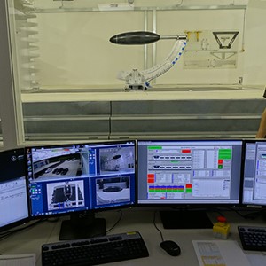
“We have significantly reduced the aerodynamic drag when compared to the prototype, reducing fuel burn and therefore operating costs and environmental impact. This drag reduction has come from modification to the hull shape. We have worked closely with the Mercedes-AMG Petronas F1 Team Applied Science Division in their wind tunnel at Silverstone. We tested a 1.3m long physical model of Airlander that enables us to add or remove ‘features’, so we could understand what works and what doesn’t. Alongside this physical testing, we have invested heavily in computer simulation of the aircraft via computational fluid dynamics (CFD) to help us scale the information from the wind tunnel up to the full-size production aircraft and to correlate the wind tunnel data to the flight test data from the full size prototype.”

Aerodynamics explained

The shape of any vehicle must be developed so that it can be propelled through the air (or water) with minimum resistance. A poor shape will result in high drag forces and the need for more powerful engines with the associated high fuel consumption, adverse environmental impact and increased operating costs.

How we analysed Airlander 10’s aerodynamic flow characteristics

The HAV aerodynamics team used a combination of CFD and wind tunnel testing.
CFD involves the use of high-performance computers and complex mathematical codes to calculate and analyse the airflow over the computer-generated models for the main aircraft components. By using CFD we were able to analyse how well the air flows over the shape of Airlander 10.

CFD

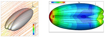
For the wind tunnel testing we worked closely with the Mercedes-AMG Petronas F1 Team Applied Science Division to carry out our testing in their wind tunnel.

"The Engineering teams from the Mercedes-AMG Petronas F1 Team’s Applied Science Division and HAV enjoyed working together to ensure that HAV’s novel test requirements were achieved in the team’s Applied Science wind tunnel."

Neil Carlisle Mercedes-AMG Petronas F1 Team Applied Science Programme Manager

The team worked with HAV to ensure the tunnel, which is usually used for testing of Formula 1 racing cars, was suitable for testing our aircraft.

Wind tunnel testing

"Testing the Airlander was an exciting first step into aerospace testing for Applied Science which introduced a few unique challenges for the engineers from both teams to resolve. Racing cars are typically tested close to the ground, whereas HAV wanted to test in the centre of the wind tunnel as that offers more representative airflow for aircraft cruise conditions (i.e. minimum effect from walls or floor)."

Neil Carlisle Mercedes-AMG Petronas F1 Team Applied Science Programme Manager

The wind tunnel testing was a success and the data produced has had a significant impact on the final design of the aircraft.

"Applied Science produced a new Airlander model and a unique support strut with the ability to progressively lower the model for investigation of ground effects on the aircraft during take-off and landing operations. HAV and Applied Science were delighted with the test results as they correlated well with previous wind tunnel and CFD data sets, providing a high level of confidence in the tunnel, test techniques and measured data."

Neil Carlisle Mercedes-AMG Petronas F1 Team Applied Science Programme Manager

How did this work feed into the Airlander 10 production design?

1. The fully retractable landing gear contributes a significant saving in drag, while improving the landing gear performance during landing and ground operations.
2. We have made changes to the aerodynamic profile of the hull, tailfins, LERX and strakes, further improving efficiency and reducing drag.
3. The removal of the forward propulsor ducts provides for lower drag once the front engines are shut down in normal flight. The duct removal also makes for quicker and more extreme thrust vectoring during take-off and landing in addition to offering weight savings.
4. The angular features of the payload module have been restyled into more rounded, aerodynamically smooth contours.
5. We modified the shape of the rear propulsor ducts, engine nacelle and vectoring vanes to improve propulsive efficiency.

Find out more about our aircraft, Airlander 10, here.

You can also find out more about the Mercedes-AMG Petronas F1 Team Applied Science division in this video, it features their work on Airlander.

Take me back to news

News and Media

Want to find out more about our technology?